This article has been moved to my new blog!
Here: https://blog.vda.https://blog.vda.io/openbsd-traffic-shaping/
In this post I will explain how to deploy a traffic shaper based on OpenBSD using PF.
The original problem was simple : a dedicated 100Mbps link had to be divided amongst several departments. Each department needed a guaranteed part of the total bandwidth and a public IP.
For example, for this article :
- The HR department needs a 10Mbps link
- The Logistic department needs two 5Mbps links
- The Security department needs two 10Mbps links
- The rest of the company will use the remaining 60Mbps bandwidth
To fulfill the needs of all the departments we need 6 + 1 IPs (6 for the different departments and 1 for our shaper). Our ISP provided us with an additional block of 14 public IPs : 33.33.33.32/28 and a free block of 2 public IP addresses : 55.55.55.52/30.
| Department | IP |
|---|---|
| Human resources | 33.33.33.34 |
| Logistic | 33.33.33.35 & 33.33.33.36 |
| Security | 33.33.33.37 & 33.33.33.38 |
| Other | 33.33.33.39 |
Our OpenBSD gateway will have the IP 33.33.33.33, the netmask is 255.255.255.240, the broadcast address is 33.33.33.47 and the network address is 33.33.33.32. We still have 7 available public addresses (40-46).
Here is a small network diagram summarizing everything :
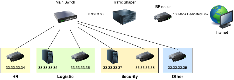
We need to have two network interfaces on our Traffic Shaper. One will be on the 33.33.33.32 network and the other will have the address provided by your ISP. The goal is to create a bridge between this two interfaces and then filter packets over this bridge with PacketFilter. Each department equipment will need to be connected to the main switch and configured with the following network configuration :
IP : 33.33.33.xx
Netmask : 255.255.255.240
Gateway : 33.33.33.33
This way, every packets will be forwarded to our Traffic Shaper on the internal interface (33.33.33.33) before going through the bridge (and PacketFilter) to the internet.
To configure our OpenBSD gateway for traffic shaping we need two main steps : building a transparent bridge and then configure our PacketFilter to do some filtering over this bridge.
Building a bridge
To build a network bridge we first need to configure the two ends : internal (33.33.33.32 network) and external (55.55.55.53).
Configuring the external interface
We will assume that em0 will be our external interface. To configure it, we need to edit the file /etc/hostname.em0 :
inet 55.55.55.53 255.255.255.252
up
Configuring the internal interface
We will assume that em1 will be our internal interface. To configure it, we need to edit the file /etc/hostname.em1 :
inet 33.33.33.33 255.255.255.240
up
Configuring the bridge
Now that we have our 2 interfaces, we will have to create a seamless bridge between them. We need to edit the file /etc/hostname.br0 :
add em0
add em1
up
We also need to enable the kernel IP forwarding ability in « /etc/sysctl.conf » : you need to find the line « net.inet.ip.forwarding=0 » and change it to « net.inet.ip.forwarding=1 ». You will have to reboot.
And that’s it ! Now, you only have to connect your em0 interface to your ISP router and your em1 interface to your main switch and the connected equipments with the good configuration should be able to access the internet.
We now have to configure PacketFilter to enforce traffic shaping.
Configuring PacketFilter
Before starting configuring PacketFilter, we must first design the bandwidth sharing policy. In this case, I decided to use a « borrow » policy to maximize the use of the total bandwidth. Basically, the limits we decided in the first place are lower limits : we guarantee that it will not fall under but we allow each department to « borrow » bandwidth from others IF it is not in use.
All the configuration for PacketFilter is done in /etc/pf.conf. The first thing to do is to define some useful aliases :
# Defining interfaces aliases
external_interface="em0"
internal_interface="em1"
bridge="br0"

# Defining allocated IP addresses for departments
HR_IP="33.33.33.34"
Logistic_IP1="33.33.33.35"
Logistic_IP2="33.33.33.36"
Security_IP1="33.33.33.37"
Security_IP2="33.33.33.38"
Other_IP="33.33.33.39"
We also need to set some options : returning a failed delivery message for unknown packets (option block-policy) and skipping all filtering on the loopback interface.
# Setting global options
set block-policy return
set skip on lo0
Next, we have to enable altq (ALTernate Queueing) on our two interfaces (for inbound and outbound traffic). We use the CBQ (Class Based Queueing) algorithm to create queue classes and enable bandwidth borrowing. We also define the names of the child queues.
# Enabling altq on internal & external interface
altq on $external_interface cbq bandwidth 100Mb queue { \
	HR_Queue_outbound, 			\
	Logistic_Queue1_outbound, 	\
	Logistic_Queue2_outbound, 	\
	Security_Queue1_outbound 	\
	Security_Queue2_outbound 	\
	Other_Queue_outbound 		\
}
altq on $internal_interface cbq bandwidth 100Mb queue { \
	HR_Queue_inbound, 			\
	Logistic_Queue1_inbound, 	\
	Logistic_Queue2_inbound, 	\
	Security_Queue1_inbound 	\
	Security_Queue2_inbound 	\
	Other_Queue_inbound 		\
}
Now, we need to define each queue both for inbound and outbound traffic. We activate the « RED » (Random Early Detection) option in order to avoid network congestion.
# Defining bandwidth limit for each outbound queues
queue HR_Queue_outbound bandwidth 10Mb cbq (borrow, red)
queue Logistic_Queue1_outbound bandwidth 5Mb cbq (borrow, red)
queue Logistic_Queue2_outbound bandwidth 5Mb cbq (borrow, red)
queue Security_Queue1_outbound bandwidth 10Mb cbq (borrow, red)
queue Security_Queue2_outbound bandwidth 10Mb cbq (borrow, red)
queue Other_Queue_outbound bandwidth 60Mb cbq (default, borrow, red)

# Defining bandwidth limit for each inbound queues
queue HR_Queue_inbound bandwidth 10Mb cbq (borrow, red)
queue Logistic_Queue1_inbound bandwidth 5Mb cbq (borrow, red)
queue Logistic_Queue2_inbound bandwidth 5Mb cbq (borrow, red)
queue Security_Queue1_inbound bandwidth 10Mb cbq (borrow, red)
queue Security_Queue2_inbound bandwidth 10Mb cbq (borrow, red)
queue Other_Queue_inbound bandwidth 60Mb cbq (default, borrow, red)
The last thing we need to do is to assign traffic to the queues we just defined :
# Assigning traffic to inbound queues
pass in quick on $bridge to $HR_IP queue HR_Queue_inbound
pass in quick on $bridge to $Logistic_IP1 queue Logistic_Queue1_inbound
pass in quick on $bridge to $Logistic_IP2 queue Logistic_Queue2_inbound
pass in quick on $bridge to $Security_IP1 queue Security_Queue1_inbound
pass in quick on $bridge to $Security_IP2 queue Security_Queue2_inbound
pass in quick on $bridge to $Other_IP queue Other_Queue_inbound

# Assigning traffic to outbound queues
pass out quick on $bridge to $HR_IP queue HR_Queue_outbound
pass out quick on $bridge to $Logistic_IP1 queue Logistic_Queue1_outbound
pass out quick on $bridge to $Logistic_IP2 queue Logistic_Queue2_outbound
pass out quick on $bridge to $Security_IP1 queue Security_Queue1_outbound
pass out quick on $bridge to $Security_IP2 queue Security_Queue2_outbound
pass out quick on $bridge to $Other_IP queue Other_Queue_outbound
This was the last thing to do, now your traffic shaper is fully configured. We still need to load the rules and activate Packet Filter :
# Loading the rule file
pfctl -f /etc/pf.conf
# Enabling Packet Filter
pfctl -e
# Disabling PacketFilter
pfctl -d
The rule file « pf.conf » will automatically be read at boot time.
Sources
- PF general documentation : http://www.openbsd.org/faq/pf/
- Networking FAQ for OpenBSD : http://www.openbsd.org/faq/faq6.html
